I was asked to take a look on a supermicro server which has been damaged by an firmware update. It was an Supermicro X10DRW-IT. The firmware update was tried by USB storage, but somehow failed.
After powering the system, it went like this:
- On with all fans for 5 sec
- Off for 5 sec
- On with all fans for 5 sec
- [..]
However it seems the IPMI is still booting through and won't be disconnected from the power as the remaining mainboard does, but the IPMI doesn't accept any bios update anymore.
As preparation I read up on the coreboot support for the Supermicro X10SLM+-F [0]
The bios chip is hidden under the raid controller if you've one.
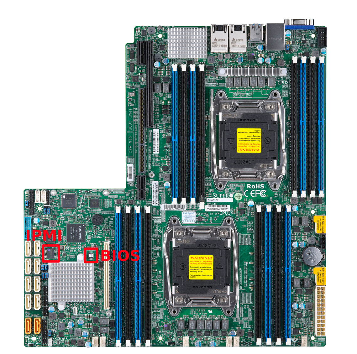
First I've taken a look on the BIOS flash. To read the bios flash out, I've used a raspberry pi 3 with a SOIC-8 clip using the SPI bus.
Required tools:
- raspberry pi with raspian (apt-get install flashrom)
- some wire cables to the SOIC8 test clip
- a SOIC-8 test clip (either the cheap ones from aliexpress or the expensive, high quality pomona 5250 [1]).
How you have to connect the SPI SOIC chip is described in [2]. Pin 1 of the SPI chip is where the small hole is on the.
Ensure you Disconnect both power supplies from the mainboard.
sudo flashrom -p linux_spi:dev=/dev/spidev0.0,spispeed=1000 -r bios
sudo flashrom -p linux_spi:dev=/dev/spidev0.0,spispeed=1000 -r bios2

sha256sum bios bios2
# ensure the checksum is equal, to ensure you read real things.

strings -n 16 bios
# try to get some strings out of it, ensure you not only read 0xffff or 0x0000.
Next I downloaded the supermicro bios update. Here you can find:
tree .

.
├── DOS
│   ├── AFUDOSU.SMC
│   ├── CHOICE.SMC
│   ├── FDT.smc
│   ├── FLASH.BAT
│   ├── Readme for X10 AMI BIOS-DOS+UEFI.txt
│   └── X10DRW9.B22
└── UEFI
    ├── Readme for X10 AMI BIOS-DOS+UEFI.txt
    ├── X10DRW9.B22
    ├── afuefi.smc
    ├── fdt.smc
    └── flash.nsh

ls -al X10DRW9.B22
-rw------- 1 lynxis users 16777216 Nov 22 16:07  X10DRW9.B22
Sound good, it's size is exact 16 MB, the same size as the bios flash. file also tell me what it is.
file X10DRW9.B22

X10DRW9.B22: Intel serial flash for PCH ROM
Great we found a firmware image with ifd (intel firmware descriptor). Now I've looked on the BIOS backup we read with the raspberry pi.
I used hexdump -C bios to see if the end contains a lot of 1s (or 0xffff in hex). Why? Because if you want to write a SPI flash, you can not just write to it like a hard drive. SPI flash chips are organised in blocks. A block is usally 64 kbyte. A single bit on a flash chip can only be written to a 0. If you want to write a single bit with a 1 where a 0 was before (0 -> 1), you've to erase the whole block, not only the address. An erase blocked is full of 1. To find out, if we have a half written flash, we can try to look on the end of the flash if there are a lot of 1s (or 0xffffffff).
hexdump -C is showing it quite nice
00c2ee20  4d 50 44 54 00 01 00 00  10 00 00 00 00 00 10 00  |MPDT............|
00c2ee30  ff ff ff ff ff ff ff ff  ff ff ff ff ff ff ff ff  |................|
*
01000000
This means, it only written up to 0x00c2ee30 (12.2 MB). Now we can look into the downloaded image, if it looks similiar. Maybe here starts configuration data. But no, it's missing some data here.
Next task is to flash the bios section. Bios section? The intel firmware description contains section. Similiar to a partition layout on a hard drive. On this platform there are 3 different sections
00000000:00000fff fd
00400000:00ffffff bios
00011000:003fffff me
- fd stands for firmware descriptor
- bios stands for the x86 firmware or UEFI
- me for the management engine (also called on servers "Server Platform Services")
To flash only the partition you either have to use a recent flashrom version (at least 1.0) or you've to extract the layout file using the ifdtool (from coreboot). You can also use the last code snipped as layout.
flashrom -p linux_spi:dev=/dev/spidev0.0,spispeed=1000 -l layout -i bios -w X10DRW9.B22
It verifies it after writing to it. But still it doesn't work. My next thought was maybe the IPMI flash got damaged as well. The SPI flash of the IPMI is close by. So let's have a look. I was lucky to also have a SOIC-16 test clip available. I did the same procedure on the IPMI flash. However the flashrom in raspian was too old. The flash chip wasn't known to this version flashrom. I had to compile it myself.
sudo apt install git build-essential
git clone https://review.coreboot.org/flashrom.git
cd flashrom
make CONFIG_ENABLE_LIBPCI_PROGRAMMERS=no CONFIG_ENABLE_LIBUSB1_PROGRAMMERS=no
./flashrom -p linux_spi:dev=/dev/spidev0.0,spispeed=1000 -r ipmi
But it looks good so far. Running binwalk on it shows us
binwalk ipmi

DECIMAL       HEXADECIMAL     DESCRIPTION
--------------------------------------------------------------------------------
103328        0x193A0         CRC32 polynomial table, little endian
1048576       0x100000        JFFS2 filesystem, little endian
4194304       0x400000        CramFS filesystem, little endian, size: 15216640, version 2, sorted_dirs, CRC 0xB1031FF3, edition 0, 8613 blocks, 1099 files
20971520      0x1400000       uImage header, header size: 64 bytes, header CRC: 0x3F1E0DA5, created: 2019-11-15 08:36:11, image size: 1537512 bytes, Data Address: 0x40008000, Entry Point: 0x40008000, data CRC: 0x310498CA, OS: Linux, CPU: ARM, image type: OS Kernel Image, compression type: gzip, image name: "21400000"
20971584      0x1400040       gzip compressed data, maximum compression, has original file name: "linux.bin", from Unix, last modified: 2019-11-15 07:25:15
24117248      0x1700000       CramFS filesystem, little endian, size: 7458816, version 2, sorted_dirs, CRC 0xF5B9463B, edition 0, 3108 blocks, 466 files
Looks also good, however I want to be sure, it's the fine. I did first a backup, second overwritten with a file from the IPMI firmware update.
Still no change.
So what's wrong here? Is the power management controller damaged? The power supply are controller digital via I2C. Maybe it's somehow telling me something is wrong?
I was lucky, I didn't had a i2c sniffer around, otherwise I would have digged into it. I nearly gave it up, before I found out, that the backup file didn't worked with ifdtool. I exported the layout using the firmware update file, and not with the backup file. Usually firmware updates do not touch the ifd. It seems server boards are different. So the backup didn't contained an ifd. It wasn't only damaged in the end, also in the beginning. Not sure if this is a safety feature of the update. It might ensure at the beginning of an update the partial flash wouldn't be recognized as a working image. It's not a good thing booting a half working image.
I flashed the bios firmware update image and the board is back. To be sure, I flashed the ipmi backup on the SPI chip.
TLDR; So the fast way to recover a partial bios, do a backup first! Then flash the full image. At least for this generation it works.
Note: Depending on your specific hardware setup (cable length, test clip) you can increase or decrease the spispeed. spispeed=10000 => 10 MHz should be still ok. You'll notice the wrong spispeed if the reading or flashing fails.
[0] https://doc.coreboot.org/mainboard/supermicro/x10slm-f.html
[1] https://www.pomonaelectronics.com/products/test-clips/soic-clip-8-pin
[2] https://github.com/bibanon/Coreboot-ThinkPads/wiki/Hardware-Flashing-with-Raspberry-Pi