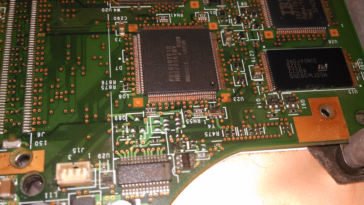
Some friends give me their old hardware to help me on my next project: Create an open source embedded controller firmware for Lenovo Thinkpads. My target platform are all Lenovo Thinkpads using a Renesas/Hitachi H8S as EC. These chips built into Thinkpads from very old one to new models like the X230.
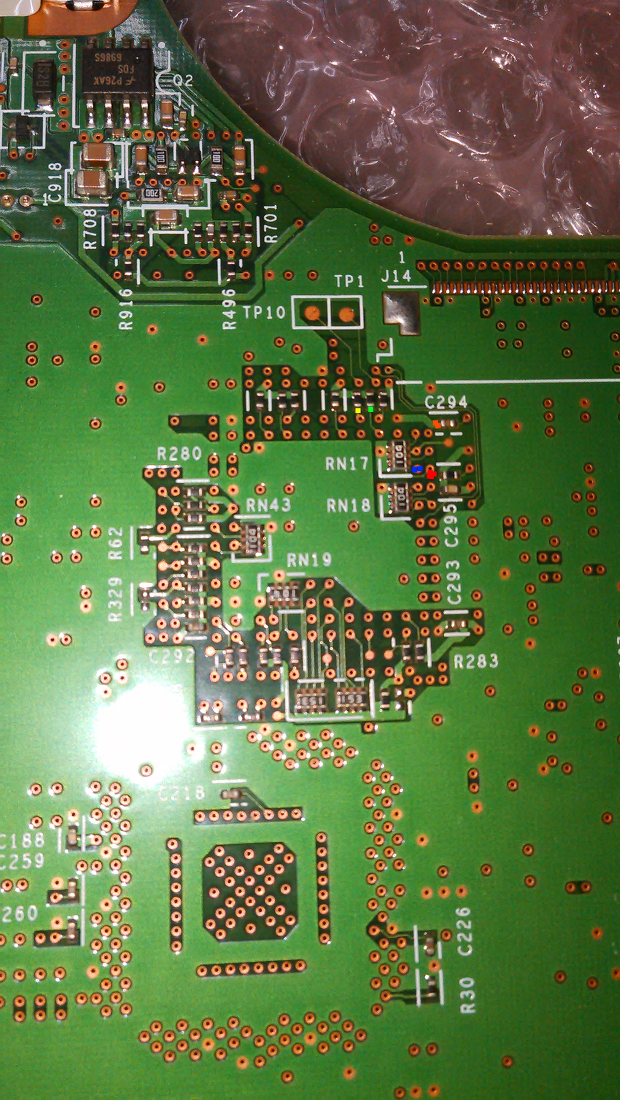
So what can be better that using a very old laptop like a T40 to solder and do hardware mods? The first step is flashing the chip independent from the Operating System running on the hardware. Why that? Because the EC controls certain power regulators and take care of turning the mainboard on. A broken EC would allow you to turn your Laptop on. The H8S supports different boot modes. It can boot normal advance boot. The boot mode is a special mode for developing and flashing. It receive their firmware over normal UART and execute it. The H8S defines it boot mode over 2 pins - MD0 and MD1 - also named mode0 and mode1. After looking on the schematics (which is available on the internet) we need to solder the UART pin RX, TX, MD1, GND. MD0 isn't required, because it's already set to 0. I soldered the test pin TP1, TP10 (I2C). /RES was soldered too, because I miscounted the pins. /RES lies beside of MD1. But it can be useful later. I colored the pins on the bottom picture.
| color | pin |
| Red | MD1 |
| Orange | GND |
| Blue | /RES |
| Green | RX |
| Yellow | TX |
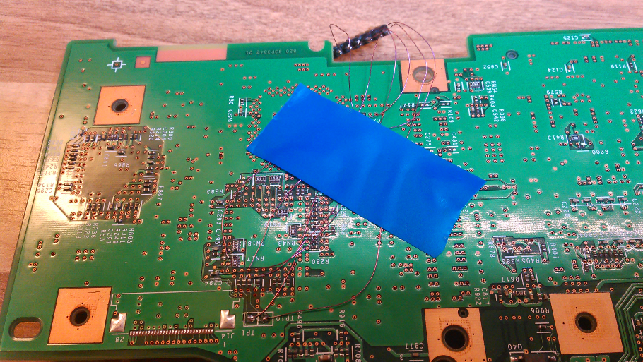
The soldered image is missing MD1.